
 1")
The device plugged into the wall is commonly called a charger, but it is not a charger at all.
An ac wall charger is a simple power adapter. Its sole function is converting high-voltage alternating current (AC) from an outlet into low-voltage direct current (AC). The actual charging circuit resides inside the electronic device. This principle of separating power conversion from battery management applies to many technologies. Even with an EV Charger, the main charging intelligence is in the vehicle, a fact that guides how EV charger manufacturers design EV charging solutions and portable ev chargers for safe charging.
The First Step: Understanding Wall Power
 2")
To understand your “charger,” one must first grasp the two fundamental types of electricity: Alternating Current (AC) and Direct Current (DC). These two forms of electrical energy power everything in our modern world, but they operate in fundamentally different ways. The power adapter’s primary job is to bridge the gap between the AC world of wall outlets and the DC world of your device’s battery.
What is Alternating Current (AC)?
The Power Grid’s Standard
Alternating Current, or AC, is the universal standard for power delivered to homes and businesses. The name describes its behavior perfectly. The flow of electricity rapidly reverses direction, oscillating back and forth. This oscillation happens at a specific frequency, measured in Hertz (Hz). The voltage and frequency of AC power vary by region.
| Region | Voltage (V) | Frequency (Hz) |
|---|---|---|
| North & Central America | 110-120 | 60 |
| UK, Europe, and most of Asia | 220-240 | 50 |
Why AC is Used for Long-Distance Transmission
Power companies choose AC for a critical reason: efficiency. Electricity loses energy over long distances. However, transformers can easily step AC voltage up to extremely high levels for transmission and then step it back down for safe use in homes. This high-voltage transmission minimizes energy loss, making AC the most economical choice for powering the grid. This is also why standard EV ac charging stations supply AC power directly from the grid.
What is Direct Current (DC)?
The Language of Modern Electronics
Direct Current, or DC, is the lifeblood of nearly all modern electronics. Unlike AC, DC flows in a single, constant direction. Think of it as a steady stream rather than an oscillating wave. This stable, unidirectional flow is exactly what sensitive electronic components, such as processors and memory chips, require to function correctly.
All battery-powered devices, from your smartphone to your laptop, operate internally on DC power. They cannot use AC directly from the wall.
Why Your Battery-Powered Devices Need It
Batteries are inherently DC devices. They store and release energy through a chemical reaction that produces a consistent, one-way flow of electrons. To replenish a battery, the charging process must supply it with direct current. This is why the concept of dc charging is so important. The power adapter converts the wall’s AC into the DC that the device’s internal charging circuit uses to safely refill the battery. Any form of battery charging ultimately relies on dc charging at the final stage.
Inside the AC Wall Charger: A Four-Step Conversion
 3")
The small brick you plug into the wall performs a complex electrical conversion in a fraction of a second. It takes the powerful, oscillating AC from the outlet and tames it into a gentle, steady DC flow that your device can use. This process happens in four distinct stages: transformation, rectification, filtering, and regulation. Let’s break down the first three steps.
Step 1: Transformation
The Role of the Transformer
The first component to act on the incoming power is the transformer. A transformer is an electrical device that transfers energy between two circuits through electromagnetic induction. In modern adapters, this is typically a very small, high-frequency transformer. Its job is to safely reduce the high voltage from the wall outlet to a much lower, more manageable level.
Stepping Down High Voltage
The transformer steps down the high AC voltage using two coils of wire wrapped around a magnetic core. This process follows a precise sequence:
- An alternating current (AC) from the wall outlet flows through the primary coil.
- This current generates a rapidly changing magnetic field within the core.
- The changing magnetic field induces a new AC voltage in the secondary coil.
- The secondary coil has fewer wire loops than the primary coil. This design difference directly reduces the voltage to a lower level, such as 5 or 9 volts, while still being AC.
Step 2: Rectification
The Diode Bridge’s Function
After the transformer lowers the voltage, the electricity is still AC, meaning it flows back and forth. Electronic devices need a one-way current. The rectifier circuit handles this conversion. Most adapters use a full-wave rectifier, commonly called a diode bridge. A diode is an electronic component that acts like a one-way valve for electricity, allowing current to pass in only one direction.
Converting AC to Pulsating DC
The diode bridge cleverly arranges four diodes to redirect the flow of AC. It forces both the positive and negative halves of the AC wave to travel in the same direction. During the negative half-cycle of the AC wave:
- Specific diodes become forward-biased, allowing current to pass.
- The other diodes become reverse-biased, blocking the current.
- This arrangement flips the negative portion of the AC wave into a positive one.
The output from the rectifier is no longer true AC. It is now “pulsating DC.” The voltage rises and falls in a series of bumps, but it never reverses direction. This bumpy signal contains an unwanted AC component called a “ripple” and is not yet clean enough for charging a device. This is a critical step for any charger.
Step 3: Filtering
How Capacitors Smooth the Power
The pulsating DC from the rectifier is too unstable for sensitive electronics. The filtering stage smooths out these bumps. The key component for this job is the capacitor. A capacitor is like a tiny, fast-acting battery. The ac wall charger uses it to store and release electrical energy very quickly. This action is vital for a stable charging process.
Creating a Stable DC Flow
The smoothing circuit uses the capacitor to fill in the voltage dips. The capacitor charges up when the rectifier’s voltage increases to its peak. It then discharges its stored energy when the rectifier’s voltage drops. This process significantly reduces the ripple, transforming the bumpy, pulsating DC into a much smoother, more constant DC flow. While not perfectly flat, this filtered DC is now clean enough for the final regulation stage, ensuring the charger provides a steady power source for the device’s internal charging system. This stable power is essential for safe and efficient charging.
Step 4: Regulation
The filtered DC is smooth, but it is not yet perfect. The final stage, regulation, acts as the ultimate quality control checkpoint. This step ensures the power delivered to your device is not just stable but also precisely the correct voltage, no matter what happens at the wall outlet.
The Regulator Circuit’s Job
The regulator circuit is the brain of the power adapter. Its job is to take the filtered DC and lock it into a constant, predefined voltage level, such as a perfect 5.0V or 9.0V. Modern adapters use a sophisticated feedback loop to achieve this.
- An integrated circuit (IC) constantly samples the output voltage.
- It compares this sample to an internal, stable voltage reference.
- If the output voltage is too high or too low, the IC instantly adjusts its operation to correct it.
This process happens thousands of times per second, guaranteeing a rock-solid output. This precision is vital for the next stage of the charging process.
Ensuring a Constant, Safe Voltage
Voltage regulators act as a critical safety net for your electronics. The power from the grid is not always stable; fluctuations like spikes (overvoltage) or sags (undervoltage) can occur due to weather or changes in electrical demand. Incorrect voltage levels can severely damage sensitive equipment.
A voltage stabilizer ensures a steady and consistent electrical voltage, acting as a protective shield for devices. Overvoltage can cause excessive heat and premature failure, while undervoltage leads to operational issues and malfunctions.
The regulator circuit shields your device from this instability. It continuously monitors the incoming voltage and makes real-time adjustments to stabilize it. For instance, a sudden voltage spike could cause irreversible damage and data loss in a computer. The regulator prevents this by clamping the output, ensuring the device only receives the correct amount of electricity. This protective action is what allows the internal charger circuit to manage the battery charging safely. A stable power supply is the foundation for reliable and efficient charging. This final step is what makes a modern ac wall charger a trustworthy partner for your device’s internal charger, protecting your investment and extending its lifespan.
So, Where is the Actual Charging Circuit?
The wall adapter provides the raw power, but it does not control the charging process. The real intelligence, the component that truly “charges” the battery, resides deep inside your electronic device. This sophisticated internal system manages every aspect of replenishing the battery, ensuring it is done safely and efficiently.
It’s Inside Your Device
Your phone, tablet, or laptop contains a dedicated circuit board responsible for all battery-related functions. This internal system is the true gatekeeper of power, making critical decisions that the simple wall adapter cannot.
The Battery Management System (BMS)
At the heart of this internal circuit is the Battery Management System, or BMS. The BMS is a small but powerful computer dedicated to one task: protecting the battery. It acts as a vigilant supervisor, constantly monitoring a wide range of parameters to maintain the battery’s health and safety. This system is a standard feature in everything from smartphones to an electric vehicle (EV). Key metrics the BMS tracks include:
- Voltage and current levels
- Temperature of individual battery cells
- State of Charge (SOC), which is the current battery percentage
- State of Health (SOH), which assesses long-term battery degradation
A Dedicated Internal Circuit
The BMS is part of a larger, dedicated internal circuit that communicates directly with the power adapter. This communication is essential for modern fast charging. The circuit uses protocols like USB Power Delivery (USB-PD) to negotiate power levels. This “digital handshake” happens in milliseconds:
- The power adapter announces its capabilities (e.g., 5V at 3A, 9V at 3A).
- The device’s internal circuit analyzes this information.
- The device requests the optimal power profile for its current needs.
- The adapter and device establish a power contract for the charging session.
This intelligent negotiation ensures the device only receives power it can safely handle.
The Brains of the Operation
The internal charging circuit is far more than a simple on/off switch. It is the brain of the entire charging operation, performing complex calculations and adjustments to maximize both speed and battery lifespan.
Monitoring Battery Health and Temperature
Continuous monitoring is the BMS’s most critical function. It keeps a close watch on the battery’s temperature, as excessive heat is a primary cause of battery degradation and a major safety risk. The BMS also tracks the electrical charge balance across different cells within the battery pack, ensuring they charge and discharge evenly. This prevents one cell from wearing out faster than others, extending the entire battery’s usable life.
The internal circuit acts as a doctor for your battery. It constantly checks vital signs like voltage, current flow, and temperature to diagnose potential issues before they cause permanent damage.
Managing Voltage and Current
The internal circuit precisely manages the flow of energy into the battery using a multi-stage charging process. The two primary phases are Constant Current (CC) and Constant Voltage (CV).
- Constant Current (CC) Phase: Initially, the circuit draws a high, steady current from the adapter. This allows the battery to absorb energy very quickly, which is responsible for the rapid charging from 0% to around 80%.
- Constant Voltage (CV) Phase: Once the battery’s voltage reaches a specific threshold, the circuit switches to the CV phase. It holds the voltage steady while gradually reducing the current. This slower “top-off” charging prevents stress on the battery cells.
Advanced systems using Programmable Power Supply (PPS) allow the device to request fine-grained voltage and current adjustments. This reduces wasted energy that would otherwise become heat, resulting in a cooler and more efficient charging cycle.
Preventing Overcharging and Damage
The ultimate role of the internal charger is protection. It uses the data from its sensors to prevent conditions that could harm the battery or the user. If the BMS detects that the battery temperature is too high, it will slow down or completely stop the charging process until it cools. Similarly, it cuts off power once the battery reaches 100% to prevent overcharging, a condition that can permanently reduce battery capacity and create safety hazards. For high-power delivery, the system even verifies that the USB-C cable has an e-Marker chip, confirming the cable can safely handle the requested current. This entire system, from the BMS in your phone to the onboard charger in an EV, is the true guardian of your battery.
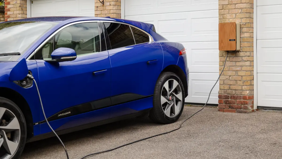
A Parallel in Electric Car Charging
The same principle that applies to your phone’s power adapter also governs electric car charging. The large unit you install on your wall or see at a public electric vehicle charging point is often mislabeled. Understanding this distinction is key to grasping how to charge your electric car efficiently.
The Misconception in EV Charging
Just like with personal electronics, the external equipment for an EV is primarily a power delivery system, not the charger itself. This is a crucial concept that guides how technologically advanced providers like TPSON design their EV charging solutions.
The “Charger” is EV Supply Equipment (EVSE)
The device you interact with, whether it’s a wall box at home or a public charging point, is technically called Electric Vehicle Supply Equipment (EVSE). Its main job is to safely supply AC power from the grid to the electric car. The EVSE acts as a smart, protected electrical outlet, communicating with the EV to ensure a safe connection before allowing power to flow.
The Real Charger is Onboard the Car
The actual charger is a component built into the electric vehicle itself. This onboard charger is a sophisticated piece of hardware responsible for the critical task of converting the incoming AC power from the EVSE into the DC power the battery needs for charging.
How AC Charging Works for an EV
The most common method for electric car charging, especially for home charging, involves this AC-to-DC conversion process happening inside the EV.
The EVSE Supplies AC Power
The EVSE, or charging station, simply passes AC electricity from the grid through its cable to the electric car. It does not perform any power conversion. It is a conduit for AC power, ensuring the connection is secure and the power delivery is stable.
The Onboard Charger Converts AC to DC
Once the AC power enters the EV, the onboard charger takes over. It rectifies and filters the AC electricity, turning it into the stable DC power required to replenish the battery pack. This internal charger also manages the charging speed and monitors battery temperature to ensure a safe and optimized charging session.
The onboard charger is the true brain of AC charging. It converts the AC supply into DC and regulates the electrical flow to protect the battery, making charging at home a safe and reliable process.
How to Charge Your Electric Car Correctly
Understanding the different levels of electric car charging helps an EV owner make informed decisions. The main types are Level 1 and Level 2 AC charging, and the much faster DC charging.
Understanding Level 1 and Level 2 AC Charging
Level 1 and Level 2 both use the car’s onboard charger to convert AC power. The primary difference is the power output and charging speed. Dedicated AC wall boxes provide Level 2 charging, which is significantly faster than using a standard wall outlet.
| Feature | Level 1 AC Charging | Level 2 AC Charging |
|---|---|---|
| Power Output | 1-3 kW | 7-22 kW |
| Use Case | Emergency or occasional use | Daily charging at home or work |
| Charging Speed | Adds 3-7 miles of range per hour | Adds 25-75 miles of range per hour |
A typical Level 2 charger can deliver 7.6 kW, allowing most EVs to fully charge overnight.
The Role of DC Fast “Chargers”
DC charging, often called “fast charging,” works differently. These powerful units are the one exception where the external equipment is the actual charger. A DC charging station contains a massive AC-to-DC converter. It completely bypasses the EV’s onboard charger and delivers high-voltage DC power directly to the battery. This direct connection enables extremely rapid charging, making it ideal for long-distance travel.
Why This Technical Distinction Matters
Understanding that the power adapter and the internal charging circuit are separate systems is crucial. This knowledge demystifies modern technologies like fast charging and highlights the importance of safety and compatibility for all your devices, from phones to an EV.
Demystifying “Fast Charging”
Fast charging is not about forcing more power into a device. It is an intelligent, negotiated process between the power adapter and the device’s internal charging circuit. This partnership enables higher charging speeds safely.
A Communication Between Adapter and Device
Modern rapid charging relies on a digital handshake. Protocols like USB Power Delivery (USB-PD) use the cable’s Configuration Channel (CC) line to establish communication. This allows the adapter and device to exchange information, a critical first step for any advanced charging session.
How a Device Requests More Power
The device’s internal circuit is the one in control. It initiates a negotiation to determine the optimal power level.
- When connected, the device and adapter communicate their capabilities.
- The device’s internal circuit analyzes its battery status and requests a specific voltage and current.
- The adapter confirms it can supply the requested power, establishing a contract for the charging session.
This dialogue ensures the device receives the correct amount of power without exceeding its limits.
The Adapter’s Role in Supplying Power
The power adapter’s role is to listen and obey. It advertises its available power profiles and delivers only what the device requests. A USB-PD adapter can offer various power levels, enabling everything from standard charging to ultra-fast charging for laptops.
| Wattage Level (W) | Supported Voltages (V) |
|---|---|
| 15 | 5 |
| 27 | 9 |
| 45 | 15 |
| 100 | 20 |
This flexibility allows a single powerful adapter to support multiple devices by adjusting its output for each one.
Safety and Compatibility
The separation of power conversion and charging management is the foundation of modern device safety. It is why you can often use different adapters without issue.
Why You Can Often Mix and Match Adapters
Because the device’s internal circuit manages the charging process, you can typically use a high-wattage adapter with a low-power device. For example, a 100W laptop adapter can safely charge a 15W smartphone. The phone’s internal circuit will simply request the 15W it needs, and the powerful adapter will oblige.
Your Device Only Draws the Power It Needs
A device’s internal Battery Management System (BMS) is the ultimate gatekeeper. It actively prevents the device from drawing excessive current.
Smart charging protocols and overcurrent protection circuits are legal requirements in many systems, including for an EV. An EV uses its onboard systems to monitor current and will interrupt charging if it surpasses a safe threshold, protecting the EV battery and equipment.
This same principle protects your phone. The internal circuit will never pull more power than it is designed to handle, regardless of the adapter’s maximum capacity. This is a key safety feature for all modern charging.
The Importance of Using Quality Adapters
While mixing certified adapters is generally safe, using low-quality or counterfeit adapters is extremely dangerous. These products often lack critical safety components.
- Overheating and Fire: Poor insulation and substandard parts can cause short circuits, leading to overheating and potential fires in both the adapter and your device.
- Device Damage: Without proper voltage regulation, a cheap adapter can send power spikes that damage the sensitive internal charging circuit of a phone or an EV.
- Electric Shock: Many counterfeit adapters fail basic safety tests for internal insulation, putting users at risk of serious electric shock.
Always use adapters from reputable brands that meet safety certifications. A quality adapter is a small investment that protects your expensive electronics and ensures safe, reliable charging. The same logic applies to an EV; using certified equipment is paramount for the safety of the vehicle and its owner.
The Evolution of the Power Adapter
The power adapter has undergone a remarkable transformation. Early designs were bulky and inefficient, while modern versions are compact, powerful, and intelligent. This evolution mirrors the advancements in the electronics they power, including the sophisticated charging systems in an EV.
From Linear Adapters to Switching Supplies
The most significant leap in adapter technology was the shift from linear power supplies to switching-mode power supplies (SMPS). This change made modern portable electronics possible.
The Old, Heavy “Wall Warts”
Older electronics used linear power adapters, often called “wall warts” for their bulky appearance. These adapters had several major technical limitations:
- They contained a large, heavy iron-core transformer.
- Their design was very inefficient, as they dissipated excess energy as heat.
- This inefficiency made them unsuitable for high-power applications.
This design was simple but wasteful, a stark contrast to the technology in a modern EV. The principles of efficient power conversion are critical for an EV.
The Modern, Compact and Efficient Adapter
Modern adapters use a switching-mode power supply. This design is far more complex but offers huge advantages in size and efficiency. An SMPS operates at a high frequency, which allows it to use a much smaller and lighter transformer. This efficiency is vital for the charging systems in an EV.
The difference in energy efficiency is dramatic. The improved efficiency reduces wasted heat, allowing for a smaller and more powerful adapter. This is the same principle that guides the design of an EV charging system.
The Rise of Universal Charging Standards
Alongside hardware improvements, standardized charging protocols have revolutionized how devices get power. This standardization is also a key goal for the EV industry.
The USB-A Era
The original USB-A port offered a basic, one-size-fits-all charging solution. It provided a standard 5V but with very limited power, leading to slow charging speeds. Each manufacturer often had its own proprietary fast-charging method, creating confusion for consumers. This fragmented approach is something the EV industry works to avoid.
USB Power Delivery (USB-PD)
USB Power Delivery, introduced with the USB-C connector, created a universal and powerful charging standard. USB-PD allows an adapter and a device to negotiate for higher power levels, enabling a single adapter to handle the charging needs of phones, tablets, and even laptops. This interoperability is a model for the EV sector.
Programmable Power Supply (PPS)
Programmable Power Supply is an even more advanced standard that works with USB-PD. It allows for dynamic, real-time adjustments to voltage and current during the charging process. This offers several key benefits:
- It enables fine-grained voltage adjustments in small, 20mV steps.
- This adaptive charging reduces energy conversion loss.
- It minimizes heat generation, which helps extend the battery’s long-term health.
This intelligent charging method is similar to the advanced battery management found in an EV, ensuring both safety and efficiency. The future of charging for all devices, including an EV, lies in these smart, adaptive systems.
An ac wall charger converts high-voltage AC power for dc charging. The true charger is the intelligent circuit inside a device, like an EV, that manages the charging. This partnership is vital for both ac charging and electric car charging, where the EV converts AC power for its battery. This knowledge helps an EV owner make smart choices for their electric car and any charger, ensuring safe dc charging and protecting the EV from unstable AC power during charging. This is the essence of dc charging for an EV.
FAQ
Can I use a laptop adapter to charge my phone?
Yes, you can. The phone’s internal circuit only draws the power it needs. A powerful laptop adapter will simply supply the lower power level the phone requests. This intelligent negotiation makes modern charging safe and versatile.
Is it safe to use any ac wall charger?
Using certified adapters from reputable brands is always the safest choice. Cheap, uncertified products often lack essential safety features like proper voltage regulation and insulation. This can damage your device or create a fire hazard.
How long does it take to charge an electric car?
The answer to how long does it take to charge an electric car depends on the charging level. A Level 2 charger used for home charging can fully charge an EV overnight. DC fast charging can add significant range in under 30 minutes.
What is the cost to install an electric car charger?
The cost to install an electric car charger varies based on your home’s electrical system and local labor rates. The installation of a Level 2 charger for an EV typically ranges from a few hundred to over a thousand dollars.
How to find electric car charging points?
An EV owner can use dedicated apps or the EV navigation system to answer how to find electric car charging points. These tools show the location, availability, and power level of each charging point, making trip planning simple.
What is the main difference between a power adapter and a charger?
A power adapter converts AC power to DC power. The actual charger is the internal circuit inside a device, like a phone or an EV, that manages the battery charging process. The adapter provides the power; the internal circuit provides the intelligence.